
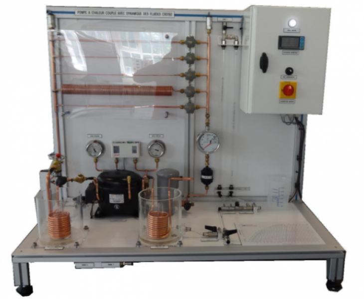
CRD 150 - Heat pump coupled with fluid dynamics
The bench CRD 150 allows to study the operation of a heat pump coupled to a fluid dynamics study.
The bench comprises an evaporator, a condenser through which a refrigerant of type R134a.
The fluid dynamics study is directly performed on the refrigerant circuit with the presence of pipes of different diameters, a sudden reduction of section and a long coil pipe.
The pressure losses will be measured using two pressure sensors. These values will transmit on a digital display and the temperature measurements.
The bench is equipped with a water supply on which is connected an orifice (diaphragm) coupled with a water column manometer and a quick-check beaker for further study of fluid dynamics.
The robust design of this equipment makes it perfectly suited for use in schools.
Its anodized aluminum structure on feet gives it great robustness as well as great flexibility of integration into your premises. The manufacturing of this equipment meets the European machine directive
Need more information?
Contact us- How a heat pump and its different components
- Use of R134a refrigerant diagram
- Draw of the refrigerating cycle on diagram (H-logP)
- Study of regular and singular pressure losses (different diameters, diameter reduction)
- Bernoulli’s Theorem using an orifice plate
- Hermetic compressor
Refrigerating production 262 W at evaporation temperature -5°C. R134a refrigerant
- Safety valve 16 bars
- Coil condenser and its water vessel
- Liquid tank
- Dehydrator filter with solid cartridge
- Flowmeter with range 50mL – 100mL/min
- Thermostatic expansion valve with internal pressure equalization
- Coil evaporator and its water vessel
- Liquid and gas indicator
- Low pressure and high pressure safety
- Piping: diameter = 1/4 and L = 50 cm
- Piping: diameter = 0.8 mm and L = 50 cm
- Coil piping 0.8 mm and L = 12 cm
- Coil piping: 1/4 and L = 12 m
- Sudden reduction of diameter: 40 1/4 cm and 10 cm in 0.8 mm
- Orifice plate to measure a ∆P
Diaphragm Ø hole = 4 mm
- Manometer with calibrated water column
- Quick-check beaker for flow rate measurement by potting
- Water circuit connected to the water system with control valve
T: Four temperature readings by thermocouple
P: Two pressure sensors 0-40 bars
BP= low pressure manometer
HP= High pressure manometer
Electrical box includes :
A white indicator of voltage presence
Multi-line digital temperature display – pressure
A switch of M/A compressor
A general power disconnect
- Power supply : 230 VAC mono – 50Hz – 20A
- Water supply : 1 to 2 L /min
- Dimensions: (LxWxH mm): 1100 x 550 x 965
- weight (Kg): 45
Other equipment that may suit you
See the full catalogue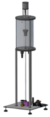
Fluid dynamics
BOR 100
Osborne reynolds apparatus
Fluid dynamics
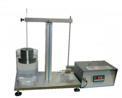
EPA 100
Archimede principle trainer
Fluid dynamics
Fluid dynamics
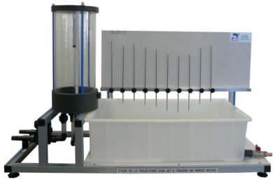
PBJ 100