
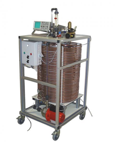
PBB 001 - Water hammer demonstration
Need more information?
Contact us- Identification of the components of a water hammer plant
- Commissioning and testing
- Demonstration of water hammer
- Determination of the speed of sound in water
- Determination of pressure drops
- Highlighting the usefulness of an anti-water hammer system
Chassis in screwed aluminum profiles
The structure is made of screwed anodized aluminum profile equipped with four directional casters with brake
Electrical box of the installation:
The machine has an electrical box that complies with European standards. It shall contain at least:
-a general power disconnector
-a 30mA differential circuit breaker
-relaying and circuit breakers necessary for operation
-buttoning and indicators necessary for operation
-an emergency stop button
- Feed tank
-Material: HDPE
-volume :100L
-outlet filter and drain valve
2. Water pump
-Discharge pressure: 2.7bar
-Maximum flow: 3.5m3/h
-manual two-pass valve to the tank
-non-return valve at output
3. Copper coil for water hammer blow
-length 70m
-Inner diameter: 12mm
4. Anti-water hammer membrane device
-manual isolation valve
5. Disruptive valves for creating the water hammer effect:
-Ball valve with pneumatic actuator
-solenoid valve
-manual ball valve
6. Float flowmeter
-reading of the water flow in the coil
-Multi-turn valve for flow control
7. Pressure measurements
-measuring point at the inlet and outlet of the coil
-one pressure gauge per point
-an analog sensor per point with output on BNC sockets for connection to oscilloscope
8. Accessory provided
-digital oscilloscope and patch cords
- Power supply: 230 Vac – 50 Hz – 6 A
- Power supply type: 1 phase(s) + Neutral + Earth.
- Water supply: tank filling
- Compressed air supply: 6-8 bars (dry air)
- Dimensions: (LxWxH mm): 700 x 1000 x 1950
- weight (Kg): 85