
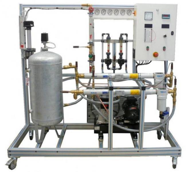
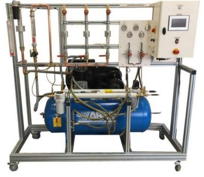
PCB 200 - Two stage air compressor
The PCB200 bench allows to study the operating principle of a two-stage air compressor.
The ambient air is drawn at the level of a filter where a diaphragm is found allowing to measure the incoming air flow by means of a manometer column.
The air passes successively through two air-water exchangers (1st stage and 2nd stage) connected to the water network of the institution.
At the output of second exchanger, the air returns in the tank then at the level of a pressure reducer connected to an output of air flowmeter to measure the output flow rate.
The robust design of this equipment makes it suitable for use in schools.
Its anodized aluminum structure on multidirectional wheels with brakes gives it a very robust as well as a high flexible integration into your premises.
The manufacturing of this equipment meets European machine directive
Need more information?
Contact us- Study and analyze the thermodynamic aspects of a two-stage air compressor
- Determine the overall efficiency, polytropic, isentropic and isothermal
- Heat balances on intermediate air-water exchangers
- Influence of the rotational speed on the efficiency
- Air flow rate measurement by a diaphragm
1. Air filter2. Measure of air flow intake for diaphragm and manometer in U
- Air compressor
- Compressor with two-stage piston
- Volume sucked to treat: 39 m3/h
- Maximum pressure: 11 bars
-
Rotational speed 1450 rev/min
4. Electric engine
- Power: 4 kW
- Rotational speed: 3000rev/min
- Engine in balance for torque measurement
-
Control of the speed of rotation by variator (from 1800 to 3000 rev/min)
5. Exchanger air-water first stage
- Tubular exchanger cooled by water (exchange at counter-current)
-
Water separator with automatic drainer at the output
6. Exchanger air-water second stage
-
Identical to the 1st stage
7. Compressed air storage tank
- Conforms to requirements of pressurized equipment
- Volume 100L
-
Purge valve at the bottom part and safety valve
8. Measurement of the flow rate of compressed air
- Automatic pressure reducer for the output pressure control (3 bar)
- Float flowmeter
- Control valve at the output and exhaust silencer
9. Instrumentation
- Ten air temperature sensors and water at different points of the installation with a multi-line digital indicator
- Six pressure manometers (at the suction and discharge of each stage, for example)
- Three safety valves
- A differential pressure manometer
- A diaphragm
- An air float flowmeter
- Two cooling water flowmeters 30 – 300 L/h
- A wattmeter
- An engine rotational speed sensor with digital indicator
- An engine torque sensor with digital indicator
- Electrical supply : 400 Vac – 50 Hz – 10 A
- Electrical network : 3 phases + Neutral + Earth.
- Water supply : 15 L/min – 2 bars
- Water drain : on the floor
- Tank air volume: 100 L
- Dimensions: (LxWxH mm): 2500 x 800 x 2000
- weight (Kg): 250
Other equipment that may suit you
See the full catalogue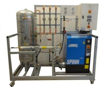
Compressors
PCB 300
Air screw compressor study unit
Compressors
Compressors
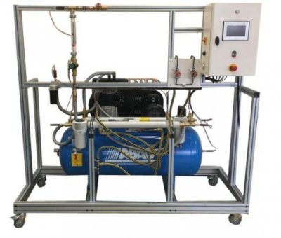
PCB 050
Two-stage air compressor trainer
Compressors