
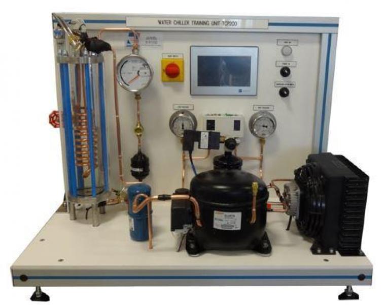
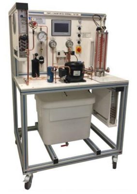
TCP 200 - Refrigeration cycle demonstration unit (water/air)
The TCP200 bench has been designed tostudy of refrigerating cycle.
The bench is made of standard elements of a refrigerating circuit. The compressor will first elevate the pressure and the temperature of the vapor (R134a). The air condenser will then transform this high pressure vapor into high pressure liquid.
The high pressure liquid will then be stored in a receiver and then be sent towards the expansion valve. This one will change the state of the fluid, it will change from a high pressure liquid to a low pressure mix (liquid+vapour). This low pressure mix is now in the evaporator and will draw its energy on the water coil (and thus cooling it). The students visualize the transformation because the refrigerant evaporates between the glass shell and the cooling coil. At the outlet of the evaporator, the fluid is in the form of low pressure vapor, it goes through a suction accumulator and will be compressed once again by the compressor.
The robust design of this equipment makes it perfectly suited for use in schools.
Its anodized aluminum structure on wheels makes it extremely robust as well as a great flexibility of integration into your premises. The manufacturing of this equipment meets the European machine directive
Need more information?
Contact us- Identification of the components of a water/air heat pump installation
- Visualization of the implementation of the system
- Visualization of the transformation of the refrigerant through glass shell (evaporation)
- Power on, use and settings
- Measurement of various operating parameters (electric consumption, temperature of refrigerants and of water, pressures)
- Energy efficiency analysis of the system and drawing of the refrigerating cycle enthalpy diagram
This unit is set up on a frame made of aluminum profile. It includes an electrical cabinet with main switch and a GFCI.
A. Hermetic reciprocating compressor 408W – 7.2 °C / 55 °C
B. High pressure gauge R134a with dual scale temperature / pressure
C. Safety valve set to 16 bars
D. Air condenser
-With forced convection
-Copper tubes and aluminum fins
E. Liquid receiver with service valve volume 0.7L
F. Drier filter
G. Sight glass
H. Flowmeter R134a with floater
-Magnetic transmission
-A needle dial
-Stainless steel construction
I. Thermostatic expansion valve with internal pressure equalization
J. Exchanger R134a/water (evaporator):
– Resistant shell glass (pressure and temperature)
– Copper coil
– Volume of the exchanger: 1.19L
– R134a fluid circulation between the shell and the coil
– Rear lighting by LED lamp (improves the visualization)
K. Suction accumulator made of steel volume 0.3L
L. Low pressure gauge R134a with dual scale temperature / pressure
M. HP and LP safety pressure switch
Integrated instrumentation:
– Low pressure gauge (R134a): -1 to 10bars
– High pressure gauge (R134a): -1 to 30bars
– Fluid flowmeter R134a: 40 to 250mL /min
– Water flowmeter: 0.2 to 1.5 L/min
– Thermocouple temperature sensor T (X10): -20 to +100°C
– Compressor power meter: 0 to 1150W
-portable anemometer
The temperatures and the power are displayed on a 7" touch screen :
- Electrical supply : 230 Vac – 50 Hz – 6 A
- Electrical network : 1 phase(s) + Neutral + Earth.
- Water supply : 1.5 L/min – 1 bars
- Water drain : on the floor
- Dimensions: (LxWxH mm): 900 x 700 x 700
- weight (Kg): 60
Other equipment that may suit you
See the full catalogue
Air conditioning
Air conditioning
Air conditioning
Air conditioning