TVP 020 - Operating principle of a pelton turbine
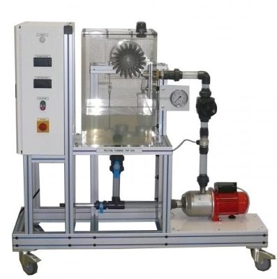
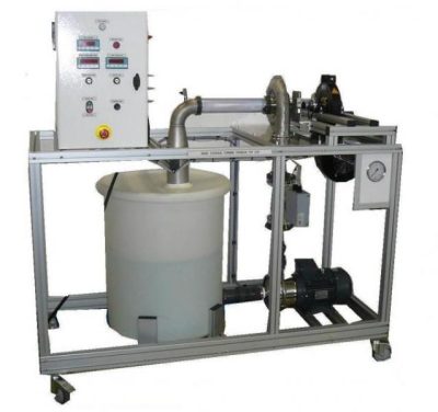
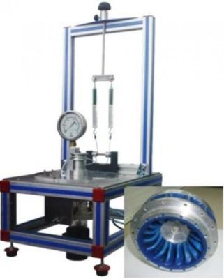
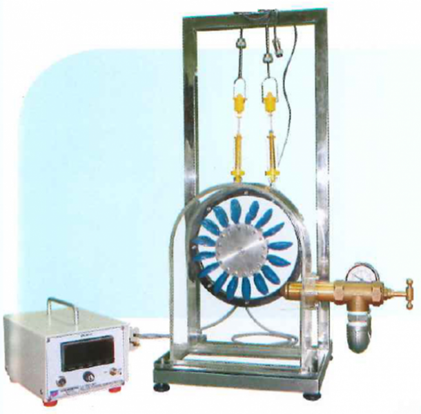
The experimental unit TVP 020 consists of the impeller, a needle nozzle used as control device, a band brake for loading the turbine and a housing with a transparent front panel. The transparent cover enables to observe the water flow, the impeller and the nozzle during operation. The nozzle cross-section and thus the flow rate are modified by adjusting the nozzle needle.
The turbine torque is determined by force measurement on a band brake and is read on spring balances. For measuring the rotational speed, a non-contact speed sensor. A manometer shows the water pressure at the turbine inlet.
The robust design of this device makes it suitable for use in schools.
The materials used are resistant to corrosion. This gives it great strength and a flexibility of integration into your laboratory.
The manufacture of this equipment complies with the European standard for machinery manufacturing
Need more information?
Contact us- In conjunction with UTL 015 or UTL 050 supply unit :
- Design and function of a Pelton Turbine
- Determination of torque, power and efficiency
- Graphical representation of characteristic curves for torque, power and efficiency
1. Spring balance
Braking force : 10 N
2. Manometer
Pressure : 0-1 bar
3. Adjustment of the nozzle cross-section,4. Needle nozzle
Jet diameter 10 mm
5. Impeller (Pelton turbine)
Output : 5W at 500 min-1, approx 30 L/min, H=2m
14 vanes for the impeller
Vane width : 30 mm
External diameter: 130 mm
6. Band brake and adjustment of the band brake
- Water supply : 30 L / min – 2 bars or supply by bench UTL 015 or UTL 050 in option (not included)
- Dimensions: (LxWxH mm): 400 x 400 x 650
- weight (Kg): 15