
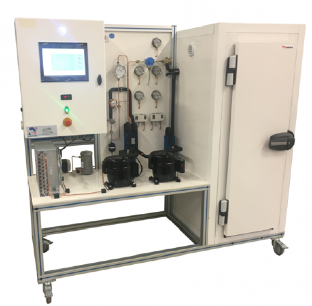
BIE 102 - Two-stage plant with partial injection
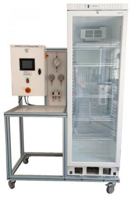
The BIE102 bench allows the study of a two-stage low-pressure refrigeration cycle.
The system allows you to visualize the two compression stages and validate the difference in performance compared to a traditional system. The students will have to commission the system and take temperature readings with different operating modes.
They will have to analyze the data and understand how the different components influence the system.
The rugged design of this equipment makes it perfectly suited for use in a school setting. Its anodized aluminum structure on wheels gives it a very high robustness as well as great flexibility of integration into your premises. The manufacture of this equipment complies with the European Machine Directive.
Need more information?
Contact us- Study of a two-stage negative refrigeration installation: compressions, condensation, expansion and evaporation, bottle, injection.
- Start-up and adjustments of a two-stage installation.
- Analysis and study of the theoretical and actual refrigeration cycle: superheating, cooling, exchanger power, component sizing.
- Calculation of the coefficient of performance (COP)
- Thermal balance.
- Enthalpy Diagram Plot
- LP Hermetic Compressor
2. HP Hermetic Compressor
3. Safety valve set to 28bar
4. Air-cooled condenser
5. Liquid Tank
6. Isolation valve
7. Injection regulator
8. Needle refrigerant flowmeter with magnetic transmission.
9. Intermediate Bottle
10. Filter drier
11. Psychic
12. Electrovanne
13. Thermostatic expansion valve with internal equalization
14. Air evaporator
15. LP Pressure Gauges
16. BP control pressure switch
17. HBP Safety Pressure Cluster
18. HP Pressure Gauges
19. Check valves
20. Pressure inverter
Structure :
All the components are assembled on a screwed anodised aluminium profile structure equipped with directional castors with brakes
Electrical box:
The electrical box is made according to the standards in force. It includes safety elements such as differential circuit breaker, master disconnect, emergency stop, grounding, buttoning, etc.
It is equipped with a 7" touch screen that displays the temperatures, the electrical power consumed, the pressures and the fluidic diagram of the machine.
A refrigeration temperature controller manages the operation of the unit, the temperature regulation of the cold room and the defrosting phases
Instrumentation :
The bench has the following instrumentation:
- Thermocouple type temperature sensors (x13):
On the refrigeration circuit:
-suction compressor
-Discharge floor 1
-Suction floor 2
-compressor discharge
-condenser output
– Interchange entrance
– exchanger outlet
– regulator inlet
-evaporator outlet
On the air:
-condenser inlet
-condenser output
-evaporator inlet
-evaporator outlet - Pressure sensors with 0-40bar analog output (x3):
On the refrigeration circuit:
-low pressure (compressor suction)
-medium pressure (intermediate stage)
– High pressure (compressor discharge) - Float Refrigerant Flow Sensor with Magnetic Transmission (x1):
On the refrigeration circuit
– Liquid line at the regulator inlet - Network analyzer for measuring the electrical power consumed by the system (x1)
- Electrical supply : 230 Vac – 50 Hz – 10 A
- Electrical network : 1 phase(s) + Neutral + Earth.
- Dimensions: (LxWxH mm): 2000 x 800 x 1850
- weight (Kg): 230
Other equipment that may suit you
See the full catalogue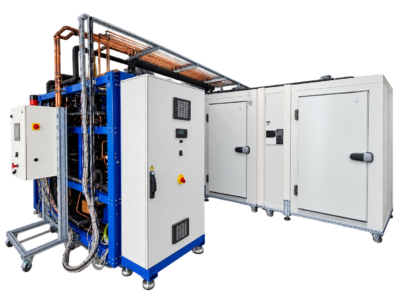
Refrigeration
BOO CO2
CO2 booster system
Refrigeration
Refrigeration
OUT 410
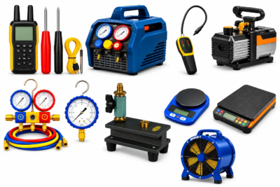
Tools kit for air conditioning
Refrigeration
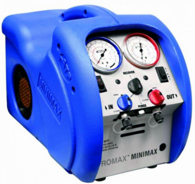
CRM 016