
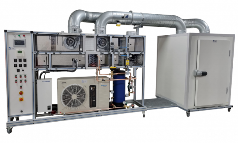
CRA 535 - Instrumented air handling unit with simulation room
The educational air handling unit (AHU) incorporates the following elements:
- An insulated box to simulate an atmosphere for air handling units;
- A system of hot and cold batteries and a humidification system to achieve a given set point in the room box (heating and humidification regulation);
- Possibility of recirculating treated air (20-100%) with manual damper or automatic regulation ;
- Ability to control each AHU component (register, cold coil, hot coil and humidifier) in manual or automatic mode
- Instrumentation for humidity and temperature measurements, as well as for electrical power measurements;
- Measurements can be taken directly on the bench or recorded in a spreadsheet file via data acquisition software that also allows real-time visualization.
The CRA535 bench allows the study of a double flow air handling unit (two fans). It consists of the classic elements of a treatment network, namely: filters, a cold coil, a chiller, a humidifier, a hot coil, a supply fan, a return fan and mixing dampers. A box is connected to the supply and return ducts to simulate a part to be regulated. The box is based on an insulated cold room to reduce heat loss
Students will first have to identify the components of the plant and the directions of air circulation.
They will then have to put the system into operation according to the conditions set by the teacher, air conditioning mode or heating mode and manual mode or automatic mode (regulation).
Once the operating regime is established, they will have to measure the operating parameters (temperature, humidity, air flow, etc.) with the fixed instrumentation.
The next task is to exploit the measurements by plotting the air cycle on a psychrometric diagram and calculating the powers of the exchangers.
Students will be able to vary the conditions and see the influence on the yields and efficiency of the system.
The rugged design of this equipment makes it perfectly suited for use in a school setting.
Its anodized aluminum structure on wheels gives it great robustness as well as great flexibility of integration into your premises.
The manufacture of this equipment complies with the European Machinery Directive
Need more information?
Contact us- Identification of the components of an air handling unit and chiller.
– Commissioning and operational checks of a power plant.
– Measurements of operating parameters (air temperature, air humidity, air velocity, differential pressure).
– Study of heat exchange and air transformation (electric hot coil, water coil, humidifier).
– Plotting the air cycle on a psychrometric diagram.
– Drawing the characteristic curve of the fan (pressure as a function of flow rate)
– Study of the refrigeration cycle and plot of the cycle on an enthalpy diagram
– Automatic control of conditions in a room
– Data acquisition by electronic sensors
- Fresh air chamber
Fresh air with inlet temperature simulation resistors
Finned heating elements
Power: 2500W
Adjustable power from 0 to 100%
2. Mixing Register
Mixing damper with electric control. The register is made up of 3 parts: fresh air, extracted air and reclaimed air
3. Filtration
A coarse filter
An fine filter
4. Cold water battery
Finned cold coil placed in the air handling duct.
Condensate drip tray in the lower part
5. Chiller and hydraulic network
Chiller with air-cooled condensation
Buffer balloon to avoid short cycles
Hydraulic network with three-way valve for regulation and instrumentation (temperature probes and flow meter)
6. Steam humidifier
Adjustable Steam Flow: 0.4 to 4Kg/h
Stainless steel steam ramp
Condensate collection in a tank
7. Electric heating coil
Upstream stainless steel droplet barrier
Finned heating elements
Power: 1500W
Adjustable power from 0 to 100%
8. Blowing fan
Fan with built-in motor
Speed variation from 2% to 100%
9. Take-back fan
Fan with built-in motor
Speed variation from 2% to 100%
10. Atmospheric box
Interior dimensions 1.2×1.2×1.6m
Insulated wall thickness 60mm
Access door with panic bar11. Instrumentation
1 pressure gauge with eight water columns for measuring static pressures on the seam
6 combined temperature/humidity sensors on the network
1 HP sensor on the GEG refrigeration circuit
1 LP sensor on the GEG refrigeration circuit
4 thermocouple probes on the refrigeration network to trace the cycle
2 fixed airflow measurement systems (supply and return)
4 Electrical powers (fresh air resistance, treatment resistance, GEG and humidifier)
All measurements except the water column pressure gauge are displayed on a 7-inch touch screen on the electrical box
12. Chassis made of screwed aluminium profiles
The structure is made of screwed anodised aluminium profile equipped with directional castors with brakes
Transparent, removable processing sheath side panels with holes for inserting probes for portable measuring devices.
13. Electrical box of the installation:
The machine is equipped with an electrical box that complies with European standards. It contains at least:
– a general power disconnect switch
– a 30mA residual current circuit breaker
– Relay and circuit breakers required for operation
– the buttonwork and the lights necessary for operation
– an emergency stop button
– Seven potentiometers graduated from 0 to 100% for the control of:
– Blowing fan
-humidifier
– Hot processing battery
– Fresh Air Simulation Battery
– Three-way valve
-register
-Take-back fan
The data acquisition system has been designed to be integrated into the central air handling bench.
It collects all the data from the system (temperatures, pressures, flow rate, etc.). The data is displayed locally on the 7-inch touchscreen and is also displayed on the software.
The software is divided into three distinct parts.
The first is the synoptic diagram of the installation with the display of all the data at the points considered.
The second is the enthalpy diagram of the refrigeration system (displayed in real time).
The third is the time-dependent plotting of the different data.
The acquisition system and its software simply require a recent PC (not included) equipped with a WIFI connection.
The acquisition system has the following specifications:
The measurements described below are displayed on a 7" touch screen locally on the machine
Measurements connected to the acquisition system:
– Temperatures and humidity:
– Temperature and humidity fresh air
– Temperature and humidity after filter
– Temperature and humidity after cold battery
-Temperature and humidity after humidifier
– Temperature and humidity blowing
– Temperature and humidity resumed
-Pressures:
-basse pression circuit frigo
– High pressure refrigerated circuit
– Temperatures on the refrigerated circuit
– Compressor suction temperature
– Compressor discharge temperature
– Temperature inlet regulator
– Temperature outlet regulator
-Flow:
– Airflow in the supply duct
– Airflow in the return duct
– GEG power consumption
– Electric power fresh air battery
– Electrical power battery treatment
– Electric power humidifier
Features of the acquisition software:
– Visualize the measurements on a synoptic diagram of the installation
– Trace of the refrigeration cycle on a real-time enthalpy diagram
– plot the evolution of the data as a function of time on a graph (each data can be selected independently)
– Save data to an Excel file
-The software is license-free.
Accessories
The system is supplied with a USB stick including the software developed in LabVIEW (installer in executable format) and the user manual.
The connection between the PC and the machine is via WIFI.
- Electrical supply : 400 Vac – 50 Hz – 32 A
- Electrical network : 3 phase(s) + Neutral + Earth.
- Water supply : 3 L/min – 2 bars
- Water drain : on the floor
- Dimensions: (LxWxH mm): 5000 x 1600 x 2500
- weight (Kg): 450
Other equipment that may suit you
See the full catalogue
Air conditioning
Air conditioning
Air conditioning
Air conditioning