
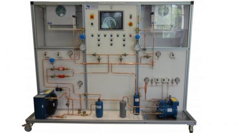
CRC 112 - Fault simulation on refrigeration system
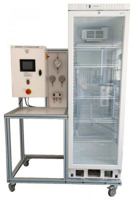
The CRC112 bench allows the study of a refrigeration cycle with double evaporator.
The system makes it possible to visualize the two refrigerated rooms and validate the difference in performance between a positive and a negative system. The students will have to commission the system and take temperature readings with different operating modes.
They will have to analyze the data and understand how the different components influence the system.
They will be able to view the refrigeration cycle in real time on the machine’s built-in PC (Panel PC).
They will also be able to find faults thanks to the system that simulates 18 faults.
The rugged design of this equipment makes it perfectly suited for use in a school setting.
Its anodized aluminum structure on wheels gives it a very high robustness as well as great flexibility of integration into your premises. The manufacture of this equipment complies with the European Machinery Directive
Need more information?
Contact us- Identifying the components of a commercial refrigeration installation
- Commissioning and adjustment
- Simulation of 18 conventional refrigeration failures
- Study of the basic concept of a refrigeration plant, with double evaporator.
- Study of the thermodynamic cycle on enthalpy diagram and real-time visualization on a computer.
- Calculation of cooling capacities for condensers and evaporators.
- Overall unit performance.
- Semi hermetic piston compressor:
-Power: 1800W approx
-Maximum working pressure: 28bar
-Starting pressure control valve (KVL) at suction
-Load control valve (KVC) between the discharge and the compressor suction.
-Safety HBP pressure switch and BP regulation pressure switch
-anti-liquid surge bottle at suction and oil recovery bottle at discharge
2. Forced Ventilation Condenser
-Pressure inverter for fan speed
3. Steel Liquid Tank
-Volume: 2.4L
4. Anti-acid filter drier (X2)
-With upstream liquid indicator light
-a filter for normal operation
-a clogged filter for failure simulation
5. Liquid Steam Exchanger (X1)
6. An exchanger for the positive chamber placed upstream of the expansion valve and on the return of the evaporator
-Two-pass valve
7. Solenoid Control Valve (x2)
-for pump down regulation
-placed upstream of the regulators of each chamber
8. Thermostatic expansion valve with internal equalization (x2)
-one for each room
-+1 fault simulation regulator for the positive chamber
9. Positive cold room with evaporator
-Forced ventilation evaporator
-condensate collection tank in the lower part
-KVP type evaporative pressure control valve
–Electronic temperature controller controlling the solenoid valve, evaporator fan and defrost
10. Negative cold room with evaporator
-Forced ventilation evaporator
-condensate collection tank in the lower part
-electric defrost resistor
-hot gas defrosting system (injection of the compressor outlet gases counter-current into the evaporator and return to the liquid tank with valve)
-Electronic temperature controller controlling the solenoid valve, evaporator fan and defrost - Dual Graduation Pressure Gauges (Fluid Saturation Pressure and Temperature)
-pressure suction compressor
– pressure discharge compressor
-Pressure liquid tank
-positive evaporator pressure
-negative evaporator pressure
12. Refrigerant flow meter before the expansion valves in each chamber
13. Thermocouple T temperature probes placed on the circuit and connected to the PC:
-Temperature suction compressor
-Temperature discharge compressor
-condenser outlet temperature
-Temperature inlet regulator 1
-Temperature inlet regulator 2
-evaporator outlet temperature 1 (negative)
-evaporator outlet temperature 2 (positive)
-temperature room 1 (negative)
– temperature room 2 (positive)
14. Panel PC
The bench has a panel PC on the front panel that is linked to the acquisition modules and allows the following functionalities:
– synoptic with measuring points
– Display of measured values (pressures and temperatures)
-activation of electrical failures
– Data logging
15. Signals from 7 temperature sensors are transferred to the front panel on thermocouple connectors
– Compressor input and output
– Condenser output
– Regulator inlet
– Evaporator output
16. The signals from two pressure sensors are transferred to the front of the enclosure on double-well bushings:
-suction compressor (LP)
-Compressor discharge (HP)
17. The bench is supplied with a portable temperature indicator compatible with the signals of the sensors used (T-type thermocouples). Cables for connecting the machine to the handheld device are provided.
- Electrical supply : 400 Vac – 50 Hz – 10 A
- Electrical network : 3 phase(s) + Neutral + Earth.
- Dimensions: (LxWxH mm): 2500 x 800 x 1940
- weight (Kg): 290
Other equipment that may suit you
See the full catalogue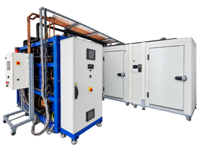
Refrigeration
BOO CO2
CO2 booster system
Refrigeration
Refrigeration
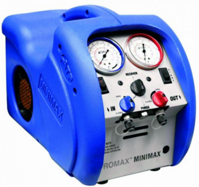
OUT 410
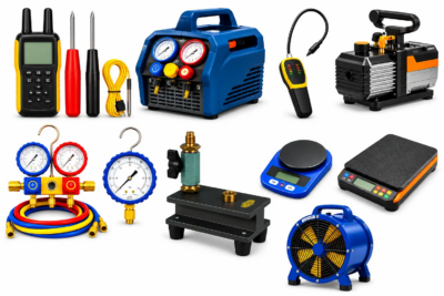
Tools kit for air conditioning
Refrigeration
CRM 016