
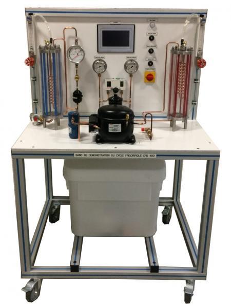
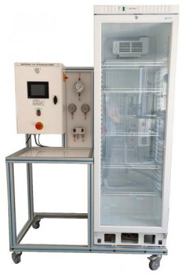
CRD 400 - Refrigeration cycle demonstration unit (water/water)
The CRD400 bench allows the study of refrigeration cycle.
The bench is made of standard elements of a refrigerating circuit. The compressor will first elevate the pressure and the gas temperature. The water condenser will then transform this high pressure gas into high pressure liquid. The students visualize the transformation because the refrigerant condenses between the glass shell and the cooling coil
The high pressure liquid will then be stored in a receiver and then be sent towards the expansion valve. This one will change the state of the fluid, it will change from a high-pressure liquid to a low-pressure mix (liquid+vapor). This low pressure mix is now in the evaporator and will draw its energy on the water coil (and thus cooling it). The students visualize the transformation because the refrigerant evaporates between the glass shell and the cooling coil. At the outlet of the evaporator, the fluid is low pressure vapor, it goes through a suction line accumulator and will be compressed once again by the compressor.
The robust design of this equipment makes it perfectly suited for use in schools.
Its anodized aluminum structure on wheels makes it extremely robust as well as a great flexibility of integration into your premises. The manufacturing of this equipment meets the European machine directive.
Need more information?
Contact us- Identification of the components of a water/water heat pump installation
- Visualization of the implementation of the system
- Visualization of the transformation of the refrigerant through glass shell (evaporation and condensation)
- Power on, use and settings
- Measurement of various operating parameters (electric consumption, temperature of refrigerants and of water, pressures)
- Energy efficiency analysis of the system and drawing of the thermodynamic cycle on the enthalpy diagram
This unit is set up on a frame made of aluminum profile with 4 wheels. It includes an electrical cabinet with main switch and differential circuit breaker.
1. Hermetic reciprocating compressor around 400W
2. Low pressure gauge with dual scale temperature / pressure
3. HP and LP safety pressure switch
4. High pressure gauge with dual scale temperature / pressure
5. Safety valve
6. Exchangers (X2):
– Resistant shell glass (pressure and temperature)
– Copper coil
– Volume of the exchanger: 1.19L
– Fluid circulation between the shell and the coil
– Rear lighting by LED lamps (improves the visualization)
7. Liquid receiver with service valve volume 0.7L
8. drier filter
9. sight glass
10. refrigerant flowmeter with magnetic transmission
11. Thermostatic expansion valve with internal pressure equalization
12. Suction accumulator volume 0.3L
13. Cooling water tank with lid:
-Material: white polyethylene
-Volume: 75L
-Drain valve at the bottom
14. Submersible pump, Body, suction strainer and turbine made of corrosion-resistant material
15. Water flow rate control valve
16. Water flowmeter (X2)
Integrated instrumentation:
– Low pressure gauge
– High pressure gauge
– Fluid flowmeter
– Water flowmeter (X2)
– Thermocouple temperature sensor T (X8): -20 to +100°C
– Compressor power meter: 0 to 1150W
The temperatures and the power are displayed on a 7" touch screen :
- Electrical supply: 230 Vac – 50 Hz – 4 A
- Electrical network: 1 live(s) + Neutral + Earth.
- Water tank volume: 70L
- Dimensions: (LxWxH mm): 1000 x 800 x 1510
- weight (Kg): 110
Other equipment that may suit you
See the full catalogue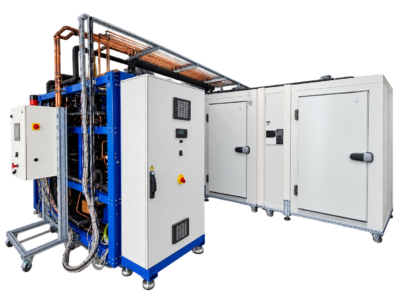
Refrigeration
BOO CO2
CO2 booster system
Refrigeration
Refrigeration
OUT 410
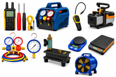
Tools kit for air conditioning
Refrigeration
CRM 016