
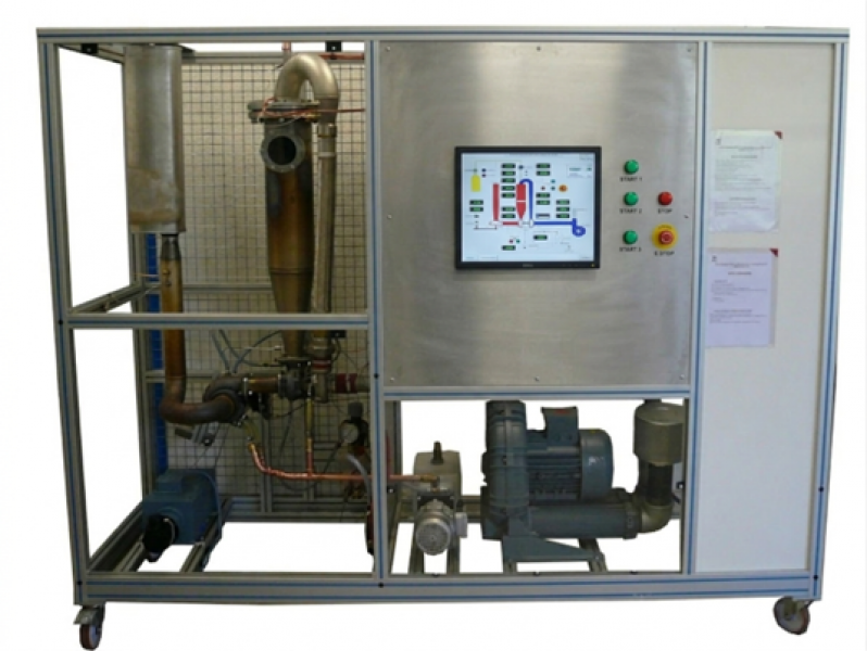
TGT 1.5 - Two-shaft gas turbine
The TGT1.5K system was developed to allow the study of a two-shaft gas turbine. The fresh air is sucked in by the compressor and sent to the combustion chamber where it will be mixed with the fuel (gas) and ignited. The expansion will drive the generator turbine which is linked to the compressor. The flow of hot gas air is then sent to the working turbine which will generate the mechanical power and drive the electric brake. The assembly is instrumented in order to be able to calculate all the efficiencies and powers of the system. The start of the turbine is automated and assisted by a fan.The machine is completely secured with emergency monitoring and shutdown elements.
The robust design of this equipment makes it perfectly suited for use in schools.
Its anodized aluminum structure on wheels gives it a very high robustness as well as a great flexibility of integration in your premises. The manufacture of this equipment meets the European Machinery Directive
Need more information?
Contact us- Study of the operation of a gas turbine with two independent propane shaft lines.
- Measurement of flow, pressure, temperature, angular velocity and torque
- Electrical power measurement.
- Efficiency of the different turbines
- Characteristics of the different components: compressor, generator turbine, combustion chamber, power turbine, electric brake
- Yields
- Security
The bench is installed on an aluminium profile structure equipped with four braked-directional castors.
It includes an electrical box with a power disconnector and a 30mA RCD.
- Centrifugal fan
Compression 0.5 to 0.7 bar
Airflow up to 300m3/h
Feed filters - Turbine generator
Single-stage centrifugal compressor
– compression ratio from 1.2 to 3
– air flow from 100 to 700Kg/h
Single-stage turbine
– wedged on the compressor shaft
– powered by the expansion of gases from the combustion chamber - Combustion chamber
Stainless steel
Air supply from the compressor
Propane supply
Propane air mixture
Electric arc ignition with high-voltage probes
Flame detection probe
4. Propane circuit
Pressure regulator
Ignition solenoid valve
Solenoid valve normal run
Propane flow meter
Injection nozzle - Power turbine
Powered by the expansion of gases coming from the generating turbine
Speed reducer
Servo motor
-max speed 3750 rpm
-max power 2 KW - Turbine lubrication plant
Distribution on the two turbine shafts
Air /oil exchanger for cooling - Measurements
7 temperature measurements
6 pressure measurements
2 flow measurements
2 turbine rotational speed measurements
1 power measurement produced - Manual settings
Propane pressure
Propane flow
Turbine speed power - Security
Combustion chamber temperature
Lubricating oil temperature
Lubricating oil pressure
Air pressure inlet combustion chamber
Turbine cooling circuit water pressure
Flame detection
Servo motor
Variable speed drive defect
- Power supply: 400 Vac – 50 Hz – 20 A
- Type of power supply: 3 phase(s) + Neutral + Earth.
- Water supply: 10 L/min – 2 bar
- Water evacuation: at ground level
- Smoke Evacuation: Diameter 200mm
- Fuel Supply: Propane
- Dimensions: (WxWxH mm): 2700 x 850 x 2000
- Weight (Kg): 780
Other equipment that may suit you
See the full catalogue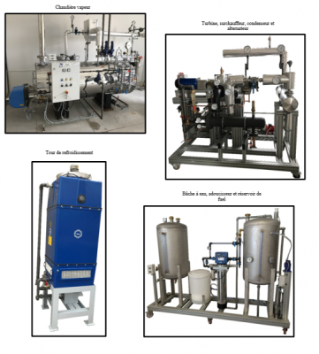
Turbines
TVT 1 kW
Steam turbine unit 1 kw
Turbines
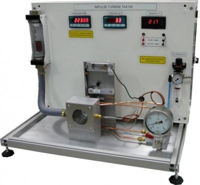
TAA 100
Impulse turbine
Turbines
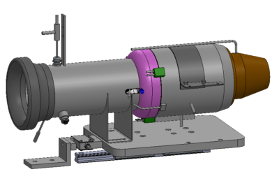
TGT 020