
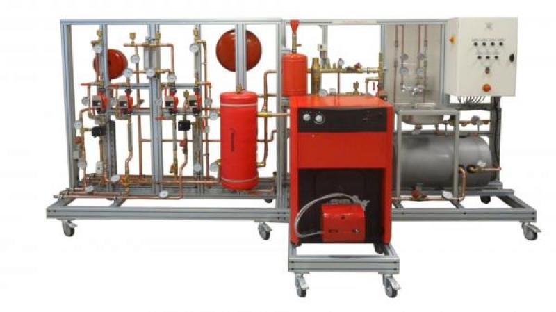
TCF 200 - House heating system
The TCF200 bench allows the study of a home heating system, it consists of a production system (fuel boiler on the ground), a primary circuit with standard components (sludge separator, circulator …), a secondary circuit "floor heating" with control valve by three-way valve , of a secondary circuit "radiator" with control valve by three-way valve , of a secondary circuit "unit heater" with separation by plate exchanger, a production circuit DHW by tank with exchanger and a sink with mixer for the use of DHW. Students will first make the system commissioning (impoundment …) then make basic measurements to validate the operation. They can then make a more complete study of the system using the integrated instrumentation (thermal balance, study of the regulation …) and the proposed optional modules.
The robust design of this equipment makes it perfectly suited for use in schools.
Its anodized aluminum structure on wheels makes it extremely robust as well as great flexibility of integration into your premises. The manufacturing of this equipment meets the European machine directive.
Need more information?
Contact us-
Identification of the components and circuits of a home heating system:
- Circuit primary heating
- Secondary circuit floor heating with V3V
- Secondary circuit radiator with V3V
- Secondary circuit unit heater with plate exchanger
- Circuit DHW by tank with exchanger.
- Commissioning of heating installation and verification of operation
- System setup and basic measurement readings (temperatures, pressures, flow rates)
- Advanced measurement and calculation of powers involved and of the consumptions
- Study of heat transfer
- Study of control systems by three-way valve
- Study of the combustion on a burner operating by fuel
The primary circuit comprises the following elements:
- A boiler working with fuel, power range: 22 to 25KW
water capacity: 103L
- An oil burner with forced air
burner power from 19 to 35KW
- Two isolation valves of the boiler
- Flowmeter on the outgoing circuit 250-2500L/h
- A dial thermometer 0/120°C on the outgoing circuit
- A mixture bottle of 25L volume with red jacket, drain valve and automatic air vent
- An injection pot with funnel and valves set. Volume 12L
- An expansion tank 25L
- Degasser sludge separator with drain valve in lower part and automatic air vent in the upper part
- Heating safety valve calibrated at 3 bar
- A pressure manometer
- A flow rate control valve (balancing valve type TA)
- Circulator 25-60 with a manometric kit
- A dial thermometer 0/120°C on the return circuit
DHW circuit includes the following elements:
- A DHW tank with exchanger with volume 80L
- DHW circulator with manometric kit
- A flow rate control valve (balancing valve type TA)
- A dial thermometer 0/120°C. at the inlet of the exchanger, at the outlet of the exchanger and tank
- A water supply line with a stop valve, meter, filter, pressure reducing and anti pollution valves
A cold water circuit with flowmeter 100-1000L/h, manometer 0-4 bars and dial thermometer 0/120°C
- A hot water circuit with flowmeter 100-1000L/h, manometer 0-10 bars and dial thermometer 0/120°C
- A mixer tap mixer
- A square stainless steel sink with siphon and overflow
The dissipation circuit N°1 (radiator) includes the following elements:
- Circulator 25-60 with a manometric kit
- A three way valve installed in apportionment
- A flow rate control valve (balancing valve type TA) on the return
- A flow sensor for regulation
- Three dial thermometers 0/120°C
- Two flowmeters 160-1600L /h
- Two bleed valves on the high points of the circuit
- Two quick couplings for connecting of the dissipation systems
The dissipation circuit N°2 (underfloor heating) includes the following elements:
- Circulator 25-60 with a manometric kit
- A three-way valve installed in mixing
- A flow rate control valve (balancing valve type TA) on the return
- A flow sensor for regulation
- Three dial thermometers 0/120°C
- Two flowmeters 160-1600L/h
- Two bleed valves on the high points of the circuit
- Two quick couplings for connecting to dissipation systems
- A safety thermostat connected to the circulator (floor protection)
The dissipation circuit N°3 (unit heater) includes the following elements:
- Circulator 25-60 with a manometric kit
- Two dial thermometers 0/120°C
- A flowmeter 160-1600L/h
- Two bleed valves on the high points of the circuit
- A brazed plate exchanger
- A hydraulic charging kit
The secondary circuit connected to the dissipation circuit N°3 includes the following elements:
- Circulator 25-60 with a manometric kit
- Two dial thermometers 0/120°C
- A flowmeter160-1600L/h
- Two bleed valves on the high points of the circuit
- A brazed plate exchanger (it is the same exchanger as the circuit N°3)
- A hydraulic charging kit
- Two quick couplings for connecting of the dissipation systems
- Heating safety valve calibrated at 3 bars
- An 8L expansion tank
- A water filling circuit with manometer and stop valve
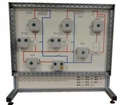
The bench has an electrical box compliant with current standards (main switch, power LED, emergency stop button and differential circuit breaker). It is equipped with switch allowing to turn on the various components (pumps, boiler …).
The terminals of the sensors (flow sensors …) and actuators (three-way valves, pumps …) are reduced on dual sink sockets on the side of the cabinet. The bench will thus be connected to RTC100 control module.
- Power supply: 230Vac – 50 Hz – 16 A
- Power supply type: 1 phase(s) + Neutral + Earth.
- Water supply : 15 L/min – 3 bars
- Water disposal: at ground level
- Evacuation of Smokes : Diameter 139mm
- Supply in Fuel: Fuel oïl
- Dimensions: (LxWxH mm): 3900 x 1550 x 1900
- weight (Kg): 400
OPTIONS :
Combustion analyzer (KIG100)
COMPATIBLE ADDITIONAL EQUIPMENT :
Fuel tank 30L (Ref : TAN030)
Unit heater dissipation bench (Ref : AER033)
Bench of radiators (Ref : TCF120)
Heated floor (Ref : TCF 121)
Bench of hydraulic balancing (radiators) (Ref : TCF122)
Briefcase of balancing TA (Ref : TCF 123)
Bench of fan coil (Ref : TCF 124)
Other equipment that may suit you
See the full catalogue
Heating
Heating
TVP 500
Steam production and supply
Heating
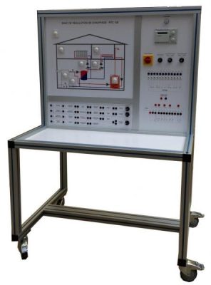
RTC 100
Heating control system
Heating
RTC 110